Week 7: Electronic output devices
- Use an output device that you haven't used before.
- Write a microcontroller program that integrates at least one input device and one output device. Avoid the delay() function by using either timers or interrupts.
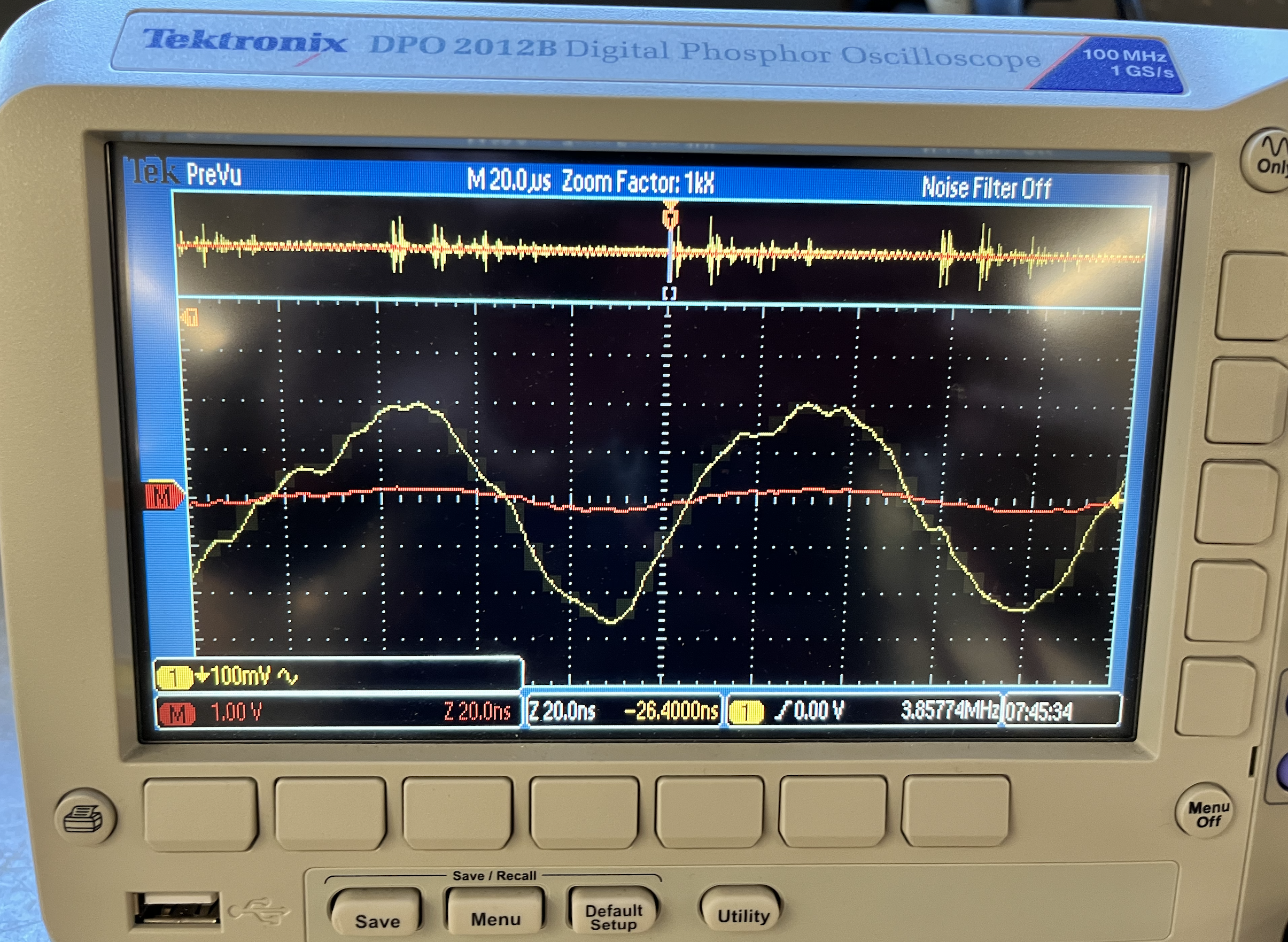
- Use an oscilloscope to discover the time domain at which your output device is operating. Is it on a fixed clock? What's its speed? Share images and describe your findings.
- Prepare CAD files for CNC week (after spring break). Consider either 2D DXF files for routing sheet material (like plywood or OSB), or 3D STL files to mill out a (2.5D) shape. We will also cover molding & casting, so you may want to consider milling a mold.
LED light slider
LED-strip-wire
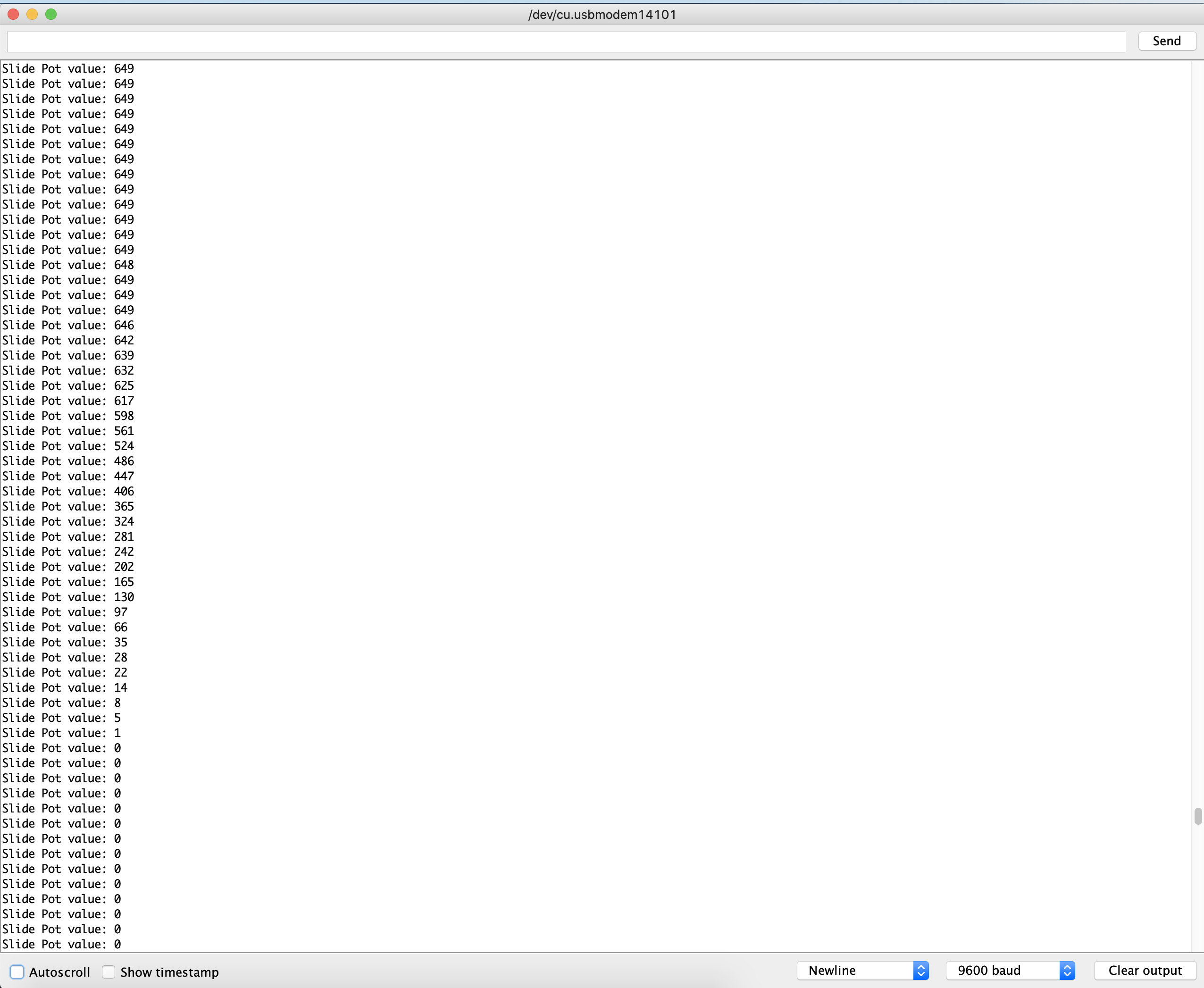
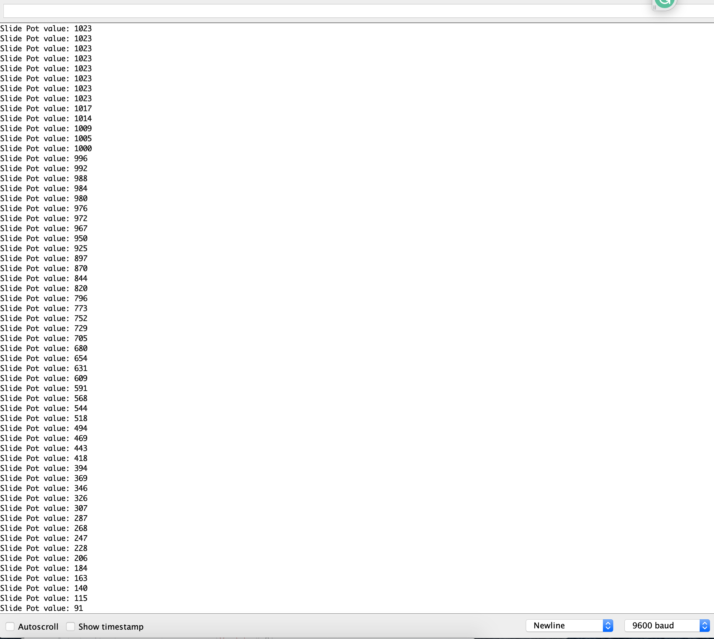
Series Monitor
Arduino LED strip code
            #include

              #define LED_PIN     7
              #define NUM_LEDS    20

              CRGB leds[NUM_LEDS];

              void setup() {

                FastLED.addLeds(leds, NUM_LEDS);

              }

              void loop() {

                for (int i = 0; i <= 19; i++) {
                  leds[i] = CRGB ( 0, 0, 255);
                  FastLED.show();
                  delay(40);
                }
                for (int i = 19; i >= 0; i--) {
                  leds[i] = CRGB ( 255, 0, 0);
                  FastLED.show();
                  delay(40);
                }
              }
              Code language: Arduino (arduino)
RGB slider
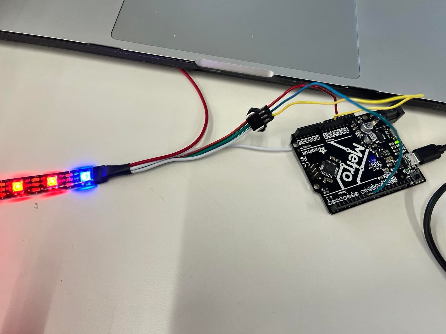
I wanted to do something with lights that I can control. I bought this slider that is very convenient and allows me to control the resistance, similar to potentiometer. The input is the slider and the output is the LED lights.I first tested out the slider input and it seems that with 5V and 3.3V, the number is different. Maximum voltage is analog-to-digital converted value and depends on the voltage level of the VCC pin.
5V = 1023; 3.3V = ~700
3.3V slider output
5.5V slider output
Wire illustration
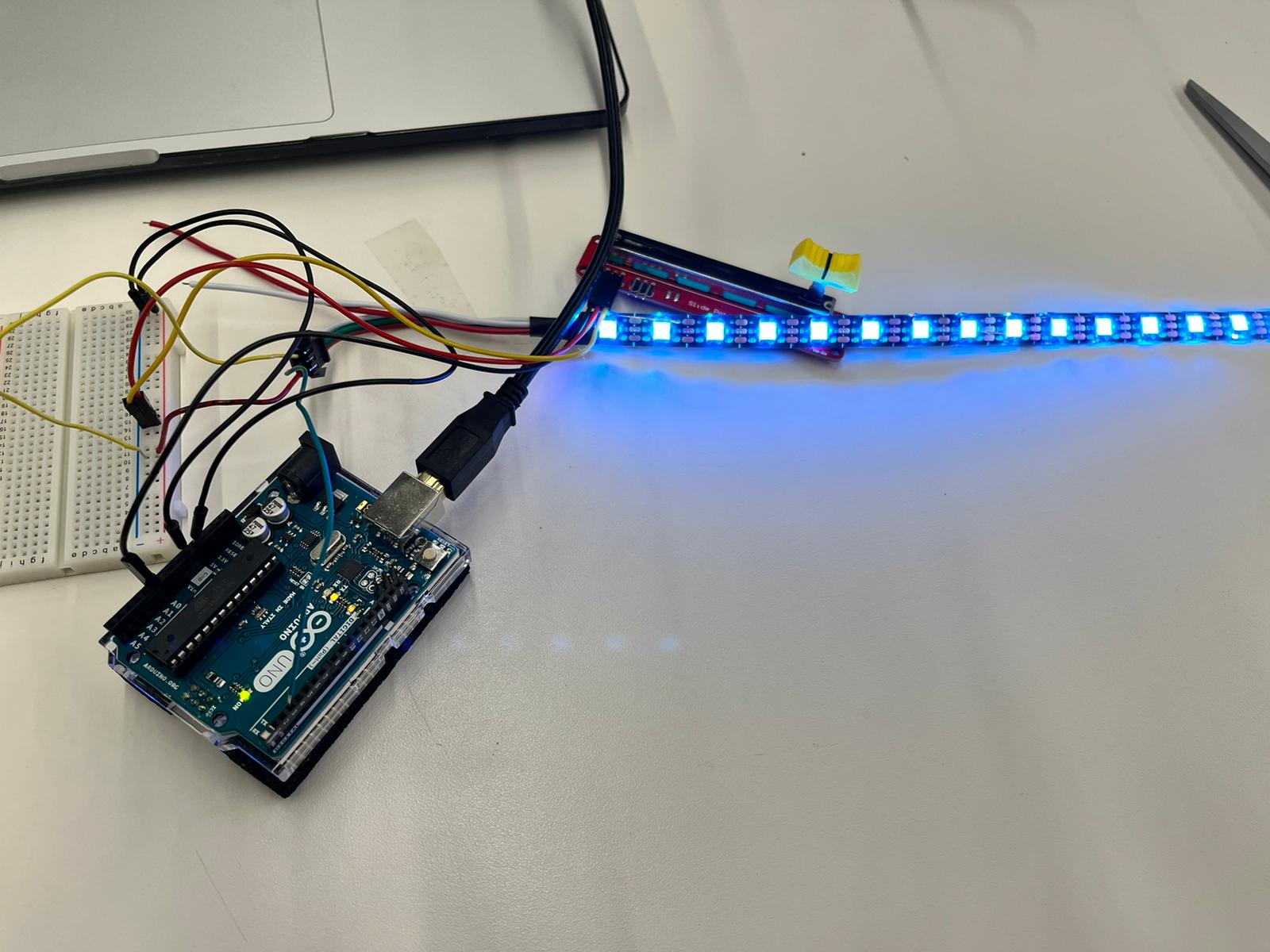
Final product
Arduino code for controlling slider
                #include "FastLED.h"

                #define PIN_SLIDE_POT_A A0 // input pin of the slide pot
                #define MAX_SLIDE_POT_ANALGOG_READ_VALUE 700

                #define NUM_LEDS 10 // add number of LEDs of your RGB LED strip
                #define PIN_LED 3 // digital output PIN that is connected to DIN of the RGB LED strip
                #define LED_COLOR CRGB::DarkOrchid // see https://github.com/FastLED/FastLED/wiki/Pixel-reference for a full list, e.g. CRGB::AliceBlue, CRGB::Amethyst, CRGB::AntiqueWhite...

                CRGB rgb_led[NUM_LEDS]; // color array of the LED RGB strip

                void setup() {
                  Serial.begin(9600);

                  pinMode(PIN_SLIDE_POT_A, INPUT);
                  FastLED.addLeds(rgb_led, NUM_LEDS);

                  Serial.println("Setup done.");
                }

                void loop() {
                  // 1) Analog value of slide pot is read
                  int value_slide_pot_a = analogRead(PIN_SLIDE_POT_A);
                  Serial.print("Slide Pot value: ");
                  Serial.println(value_slide_pot_a);

                  // 2) Analog value is mapped from slide pot range (analog input value) to led range (number of LEDs)
                  int num_leds_switchedon = map(value_slide_pot_a, 0, MAX_SLIDE_POT_ANALGOG_READ_VALUE, 0, NUM_LEDS);


                  // 3) Light up the LEDs
                  // Only LEDs are switched on which correspond to the area left of the slide knob
                  for (int i = 0; i < num_leds_switchedon; ++i) {
                    rgb_led[i] = LED_COLOR;
                  }
                  // LEDs are switched off which correspond to the area right of the slide knob
                  for (int i = num_leds_switchedon; i < NUM_LEDS; ++i) {
                    rgb_led[i] = CRGB::Black;
                  }
                  FastLED.show();
                }
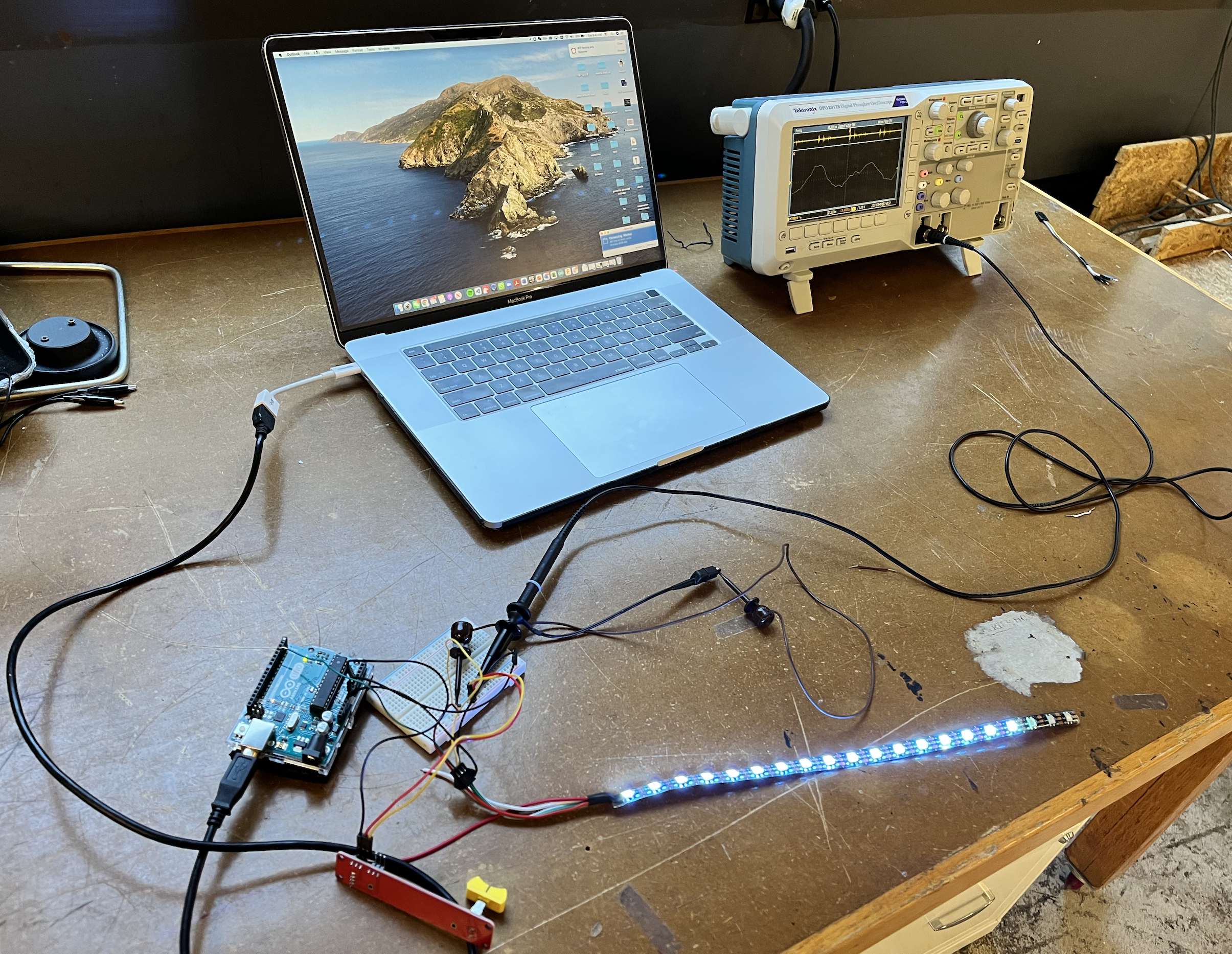
oscilloscope
It took me a while to figure out how to make the oscilloscope work. In the beginning, I'm only getting noises.
oscilloscope
Wire Connect
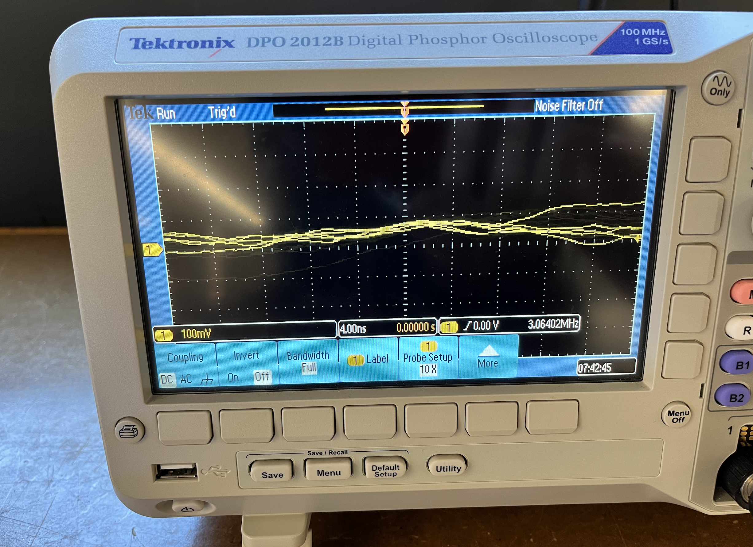
Here are some of the failed/unsuccessful oscilloscope graphs.
oscilloscope Failed one
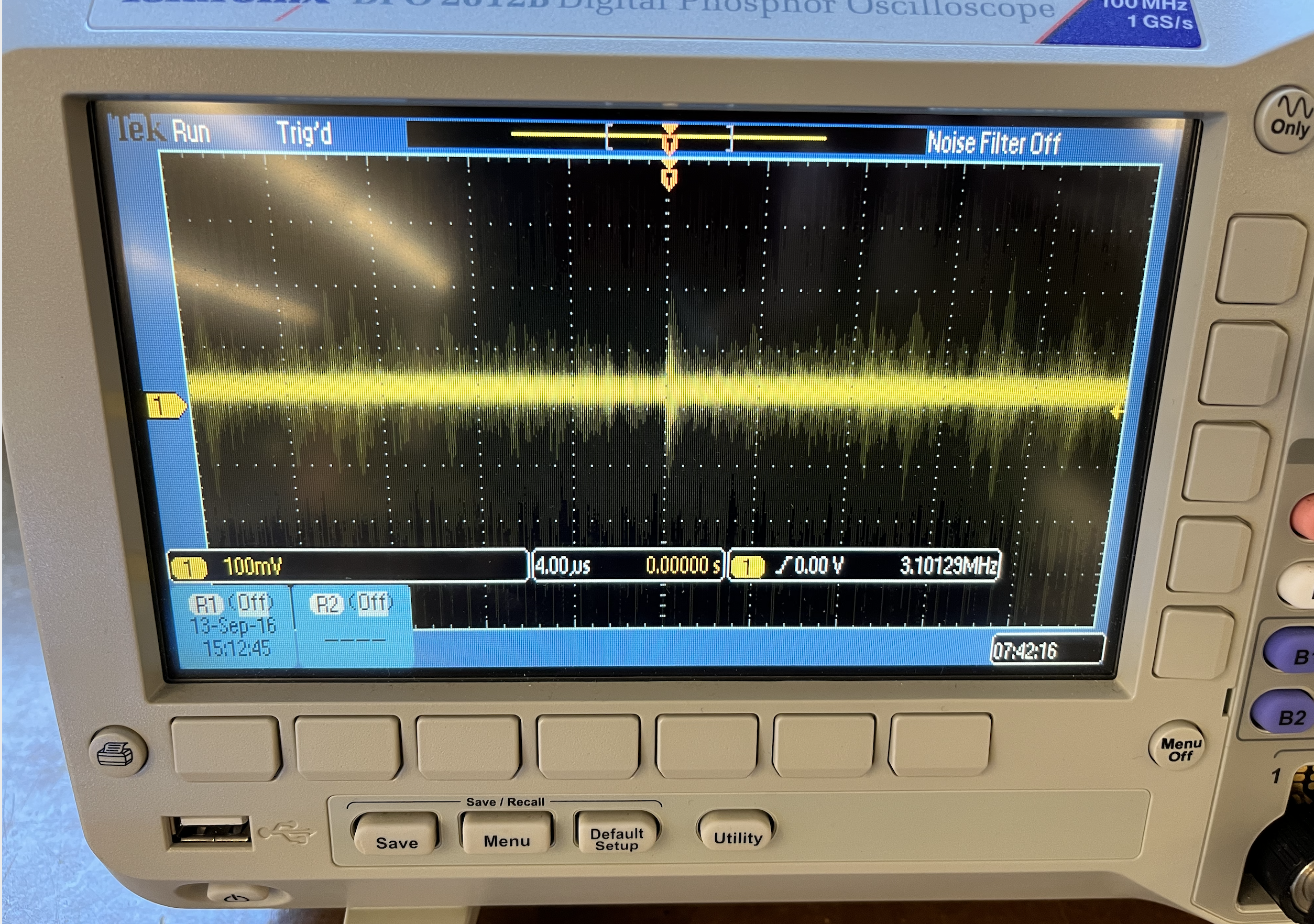
oscilloscope Failed two
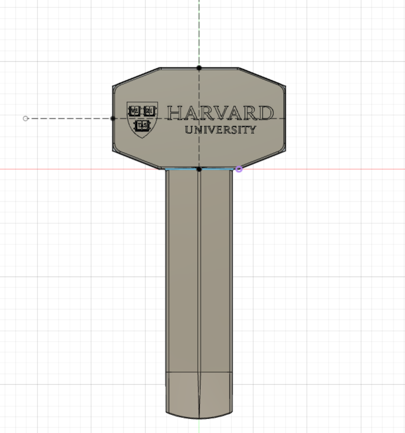
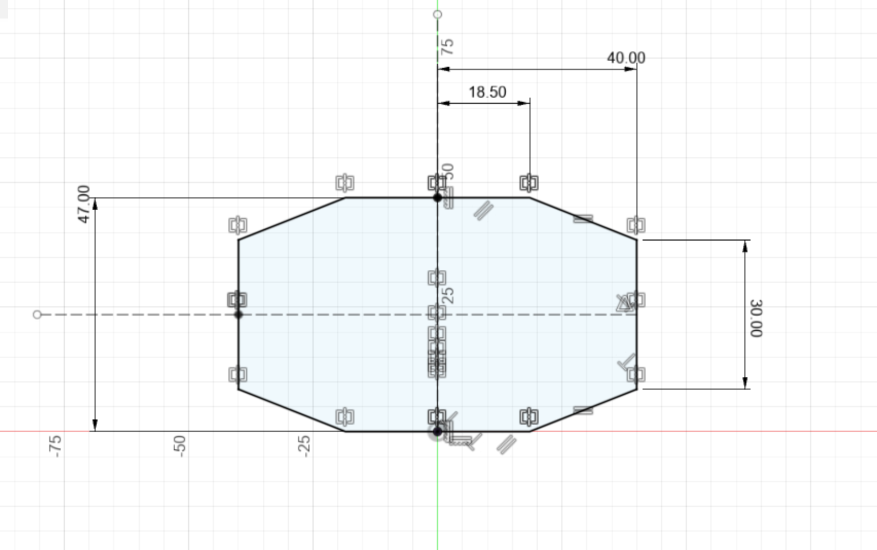
CNC molding file in Fusion 360
Then I followed a tutorial online to make a CNC molding file in Fusion 360. I learned a lot of new tricks for designing in Fusion 360 from this tutorial. For instance, I learned circular pattern, how to put a svg to the design and extrude it When and how I should do fillet.
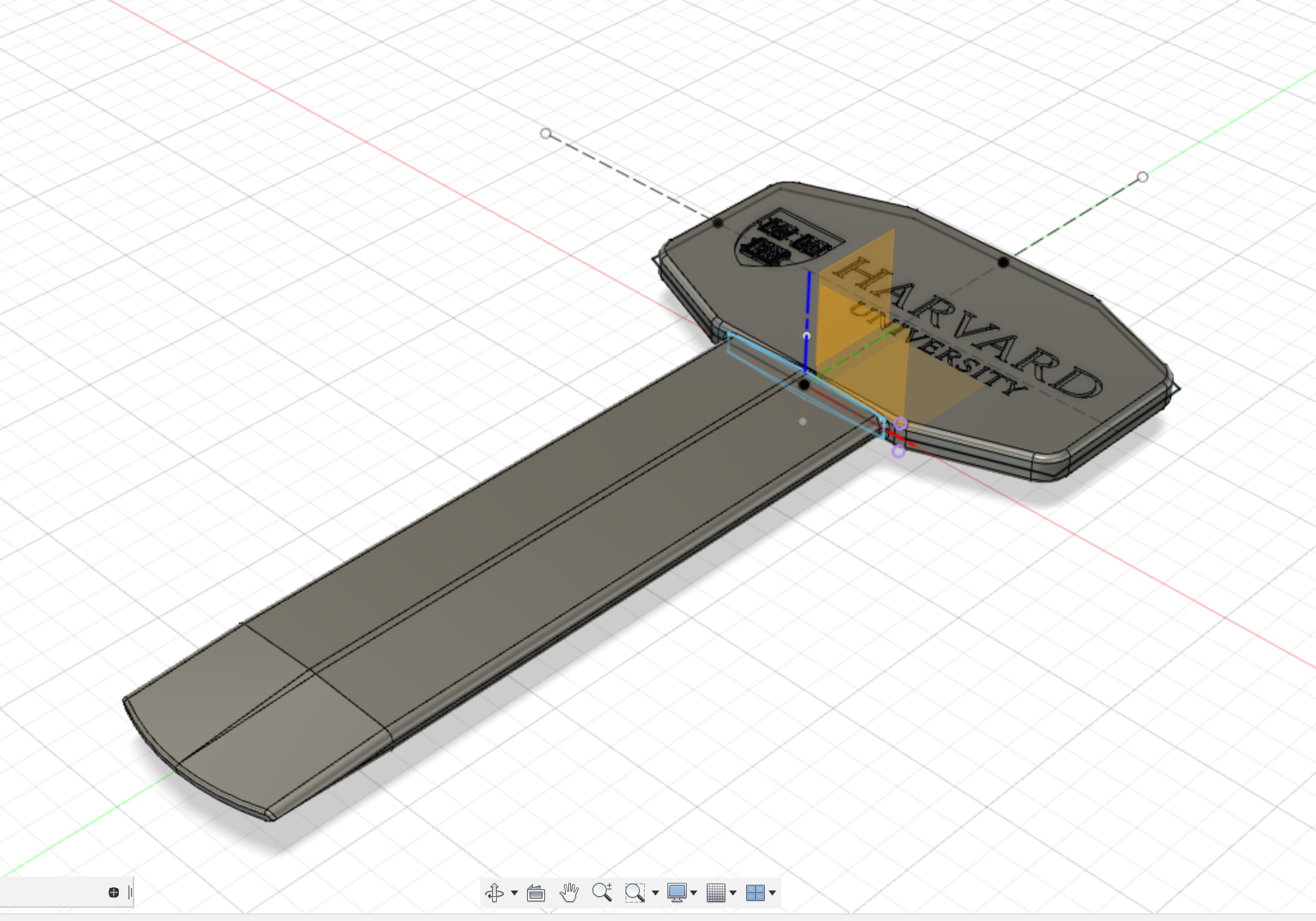
Final Product
circular-pattern
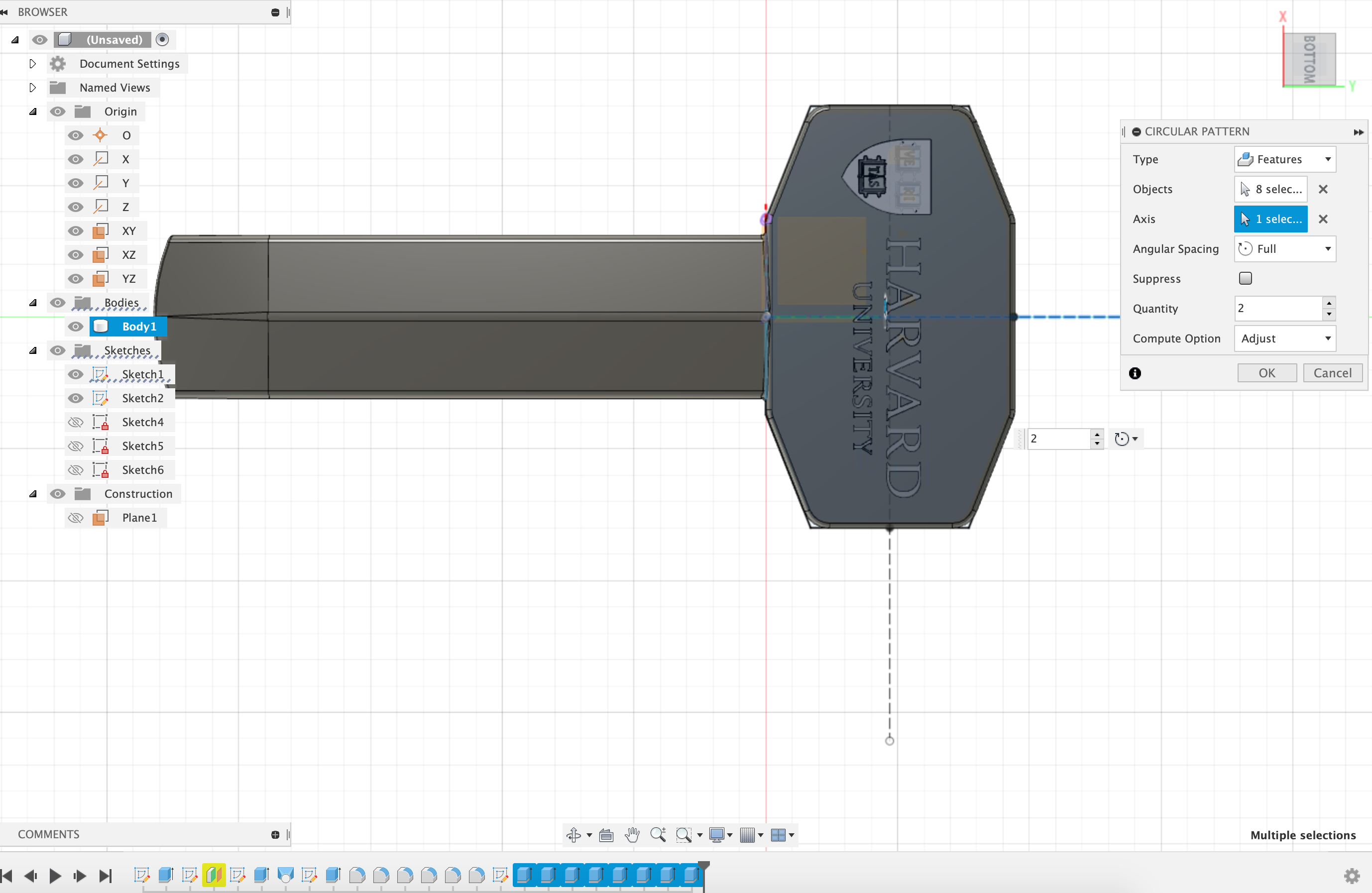
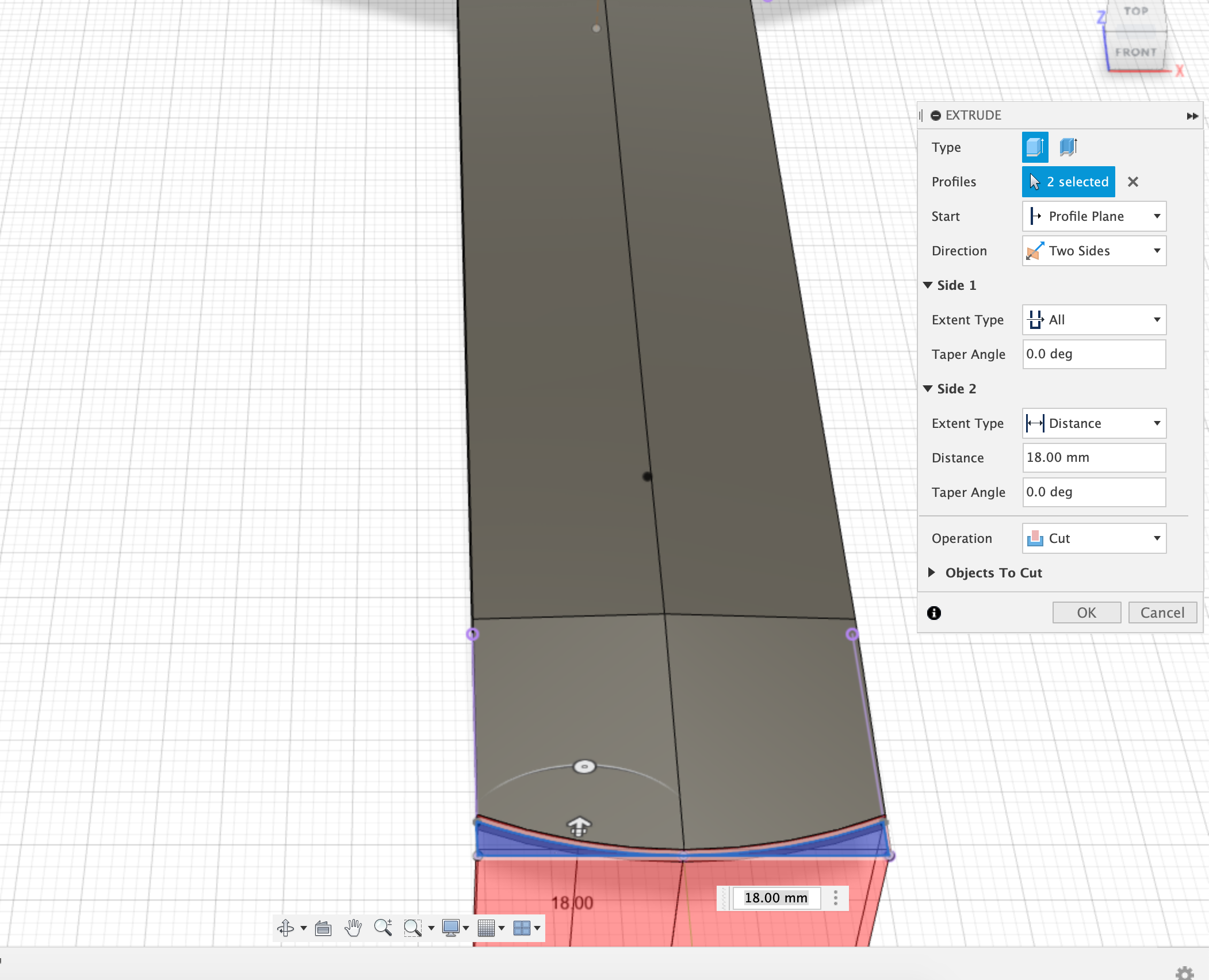
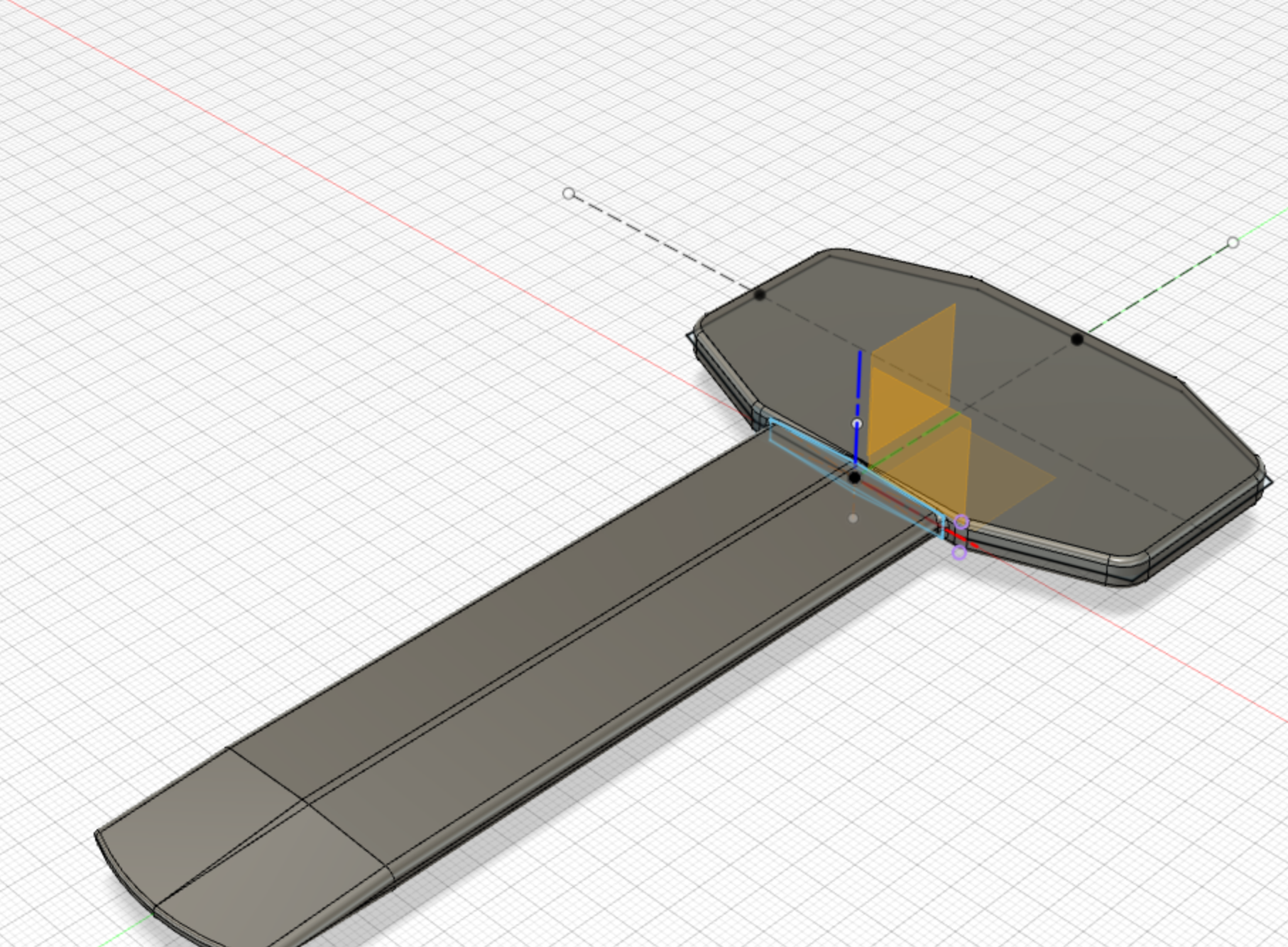
Here are some of the screenshots of techniques I used when designing.
Extrude
Fillet
Side view
Sketch
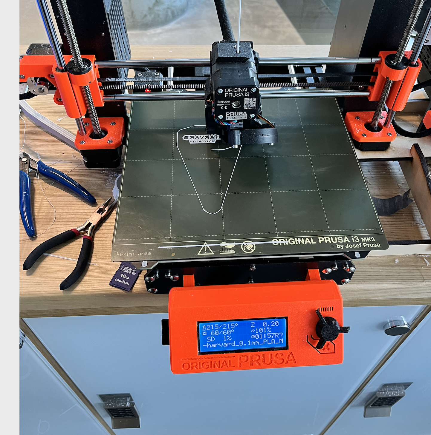
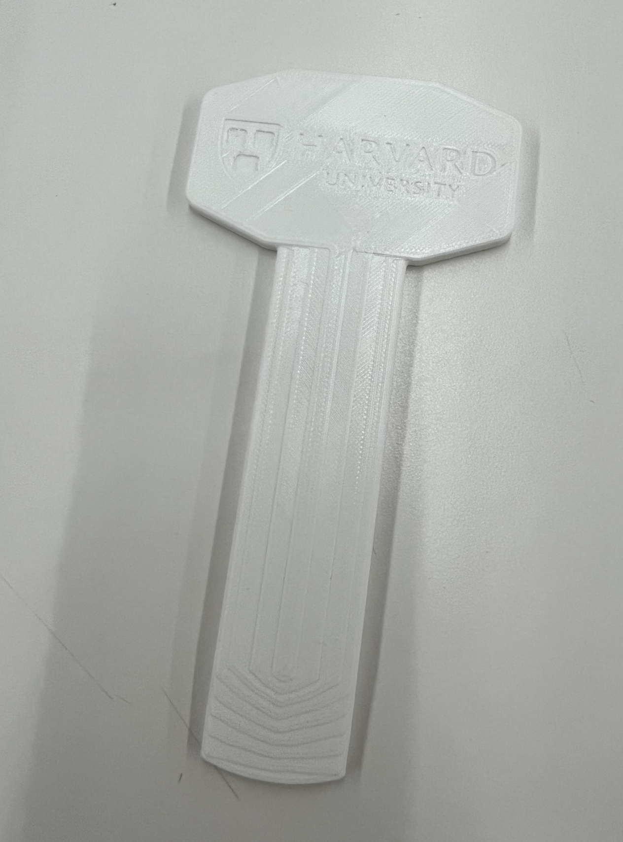
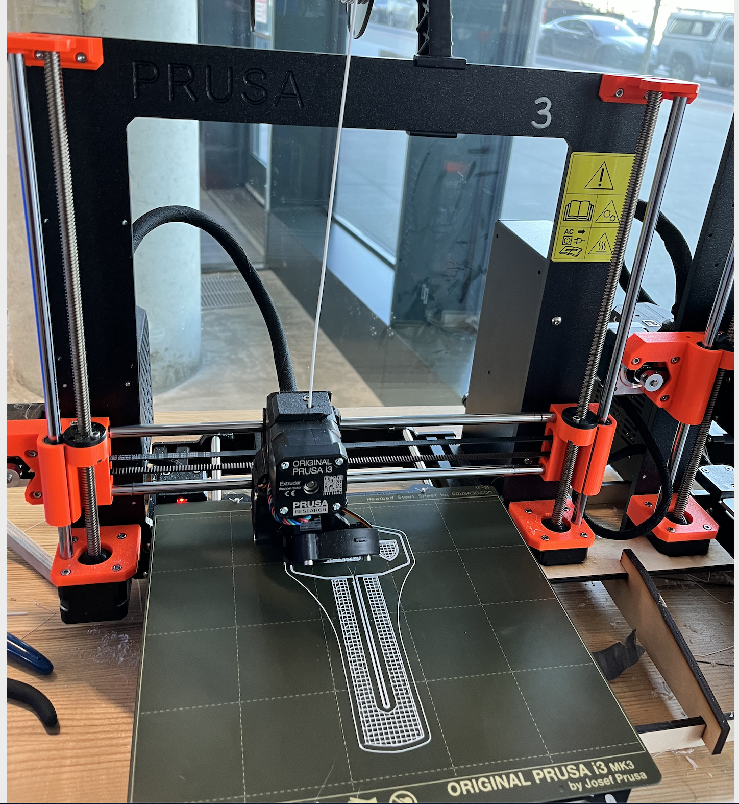
Then I 3D printed this, as I want to see the difference between 3D printing, CNC milling for next week. Interesting, I encountered some difficulties when 3D printing. Originally, I wanted to save materials by not applying support. And I feel my part is so flat that it doesn't need support. However, it turned out the item didn't attach to the board and jammed in the middle (glad I checked that!) And it was only 2 hours print.
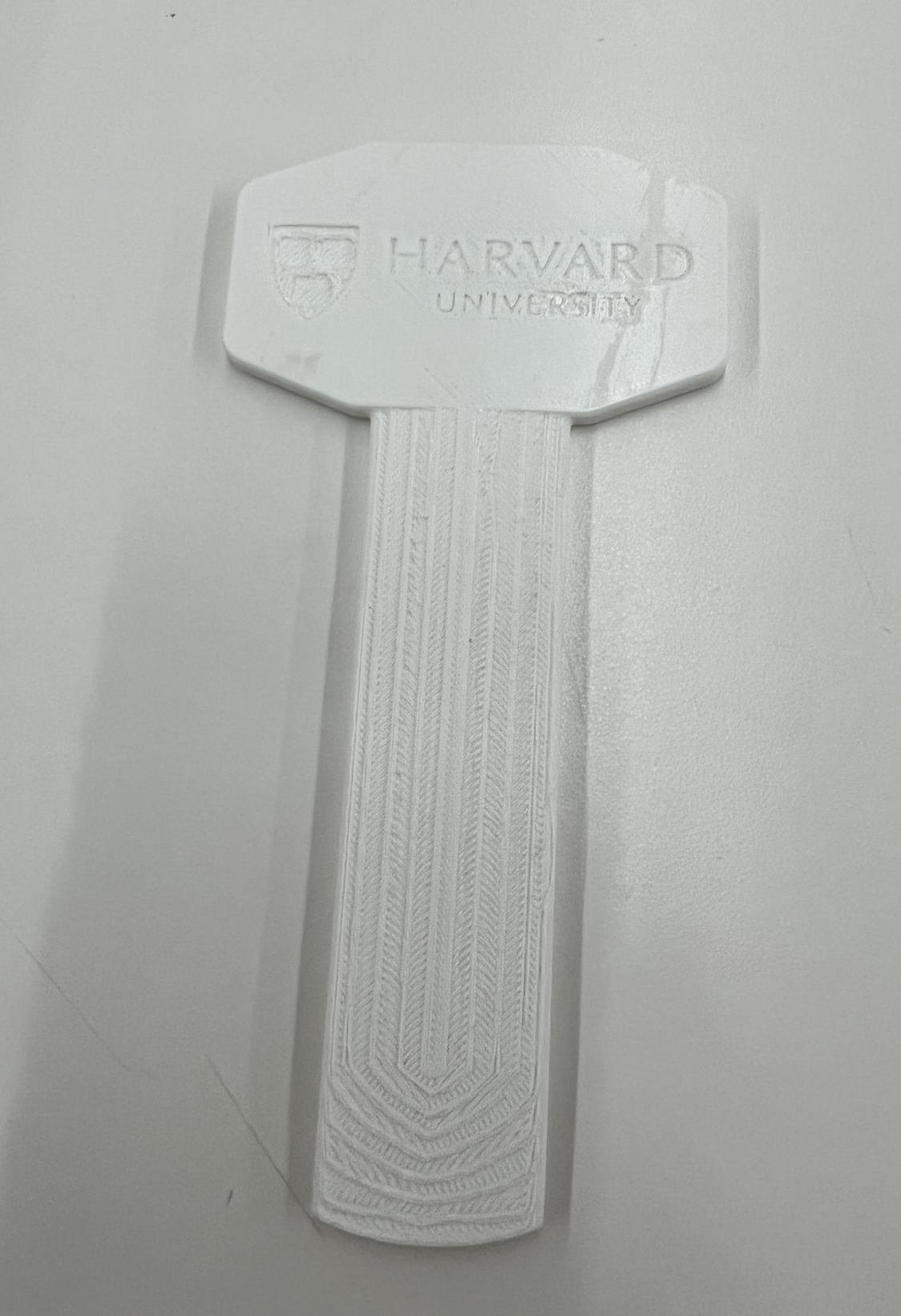
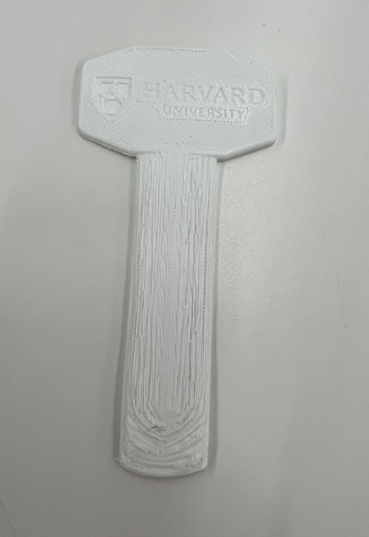
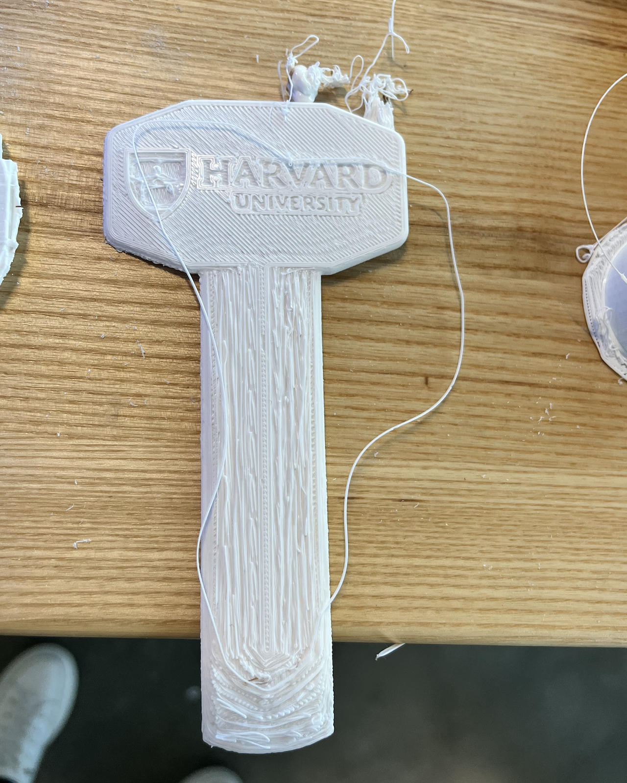
Here's the successful print.
Success Front
Success Back
Success support material applied
Here's the unsucessful one and some failed pictures.
Failed Back
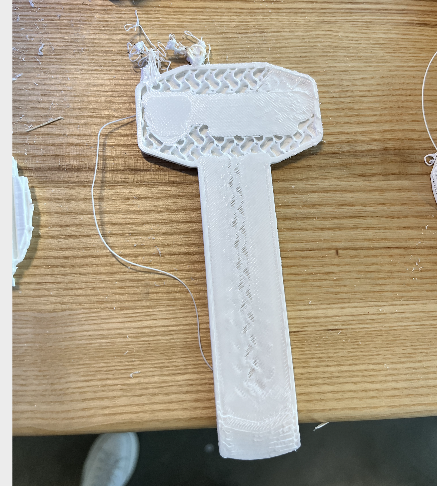
Failed front
Failed no support
First few layers